Background
High power together with good low-end RPM behavior can be achieved when using modern engines as a base of tuning project. The engine of this story can be found from Fiat Marea, Bravo and Brava or Lancia Delta, years 95...99.
This engine is derived from the SOHC unit of Fiat 128, Uno, Ritmo, Regata and some small Lancias. The first model was the 55bhp engine 128A.000 of Fiat 128. However, the heads are not interchangeable because some head bolts are relocated. On this new engine, the head bolts are symmetrically aligned with the centerline of the bores, which is good for ruggedness. Additionally, there is oil return passages on both sides of the head.
A provision for block-mounted distributor, type of the waterpump and presence of auxiliary shaft bring the old 128 engine to mind.
My goal is to install this engine into my 127. With the bottom end de-stroked to 1301cc (using SOHC 1.1 or 1.3 NA crank), this should be possible even in Finland when using this particular 90bhp version 182A6.000. (The sick rules of engine swaps in this country are described in the 127 mainstory). However, nothing is sure and that's why this engine has it's own pages...

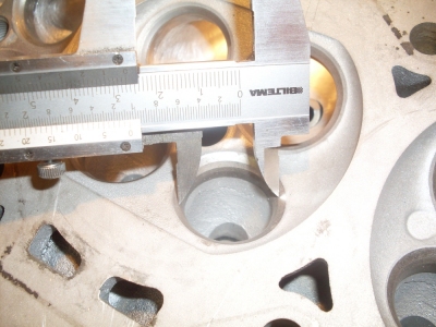
In the picture above, a 16v head gasket is placed on the SOHC block. Misalignment of passages and bolt holes is shown.
The project engine
I purchased a 1.6 16v engine after long seeking. A spare head was also included. The engine has done 80tkm (50t miles) and it is in very good condition. Oil pump and valve tappets are missing. The stock tappets are hydraulic and they seem very similar to the ones used on Saab 16v engines. I would like to have mechanical tappets, that suit better for a highly tuned engine... the tappet diameter is 33mm, anything else can be done by machining because this engine has separate camboxes. From somewhere I heard that some Subaru turbo engines would have suitable ones, but this is not yet confirmed.

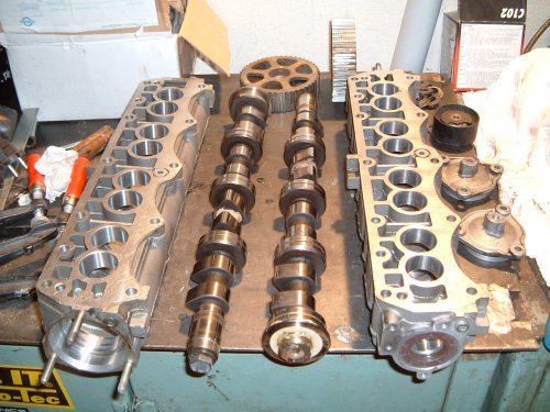

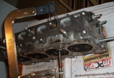
Stripping the cylinder head
The cylinder head was put in parts and after that, all components were washed and cleaned. It is better to work on clean cylinder head!

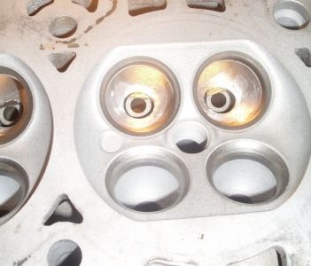
Modifications of the cylinder head - intake side
Modern 16v cylinder heads usually don't require much modifications. The inner diameters of intake valve seats may be too small compared to the valve sizes, but this was not the case with this head. Actually, the diameter of intake port venturi was even slightly too large. Smoothing the port surface is all that is needed to do.


The diameter of intake valve is around 29mm, so suitable inner diameter of the valve seat is 26mm. The intake port should be 24mm in diameter of the venturi. Measuring the port is done with a gauge shown by the pictures above.
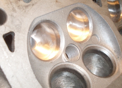
Shaping the intake valve pockets was started. The modifications will aim to a smooth and concentric turn from the valve pocket to the port. Valve pockets were also widened, and port roof was raised a little near the valve guide.


After all the material needed was removed, the port surface was finished. Roughness of the valve pocket is removed with die grinder stone and after that, 80-grit flapwheel is used. This leaves even too shiny port wall.
The optimum surface quality is achieved by grinding by finger, using a piece of emery cloth. However, the job will be easier if using a specially made tool for it, driven slowly by an electric drill. The tool is made from a piece of shaft (10mm diameter) that is cut split from one end, to hold the emery cloth in place. A picture of such tool is shown below.
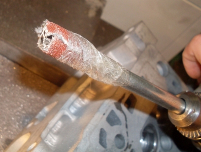

Finishing the actual port is done with emery cloth attached to 6-mm-dia shaft in similar way (grade 80). It is operated with die grinder. The emery cloth will wear out wery rapidly so it must be changed regularly.


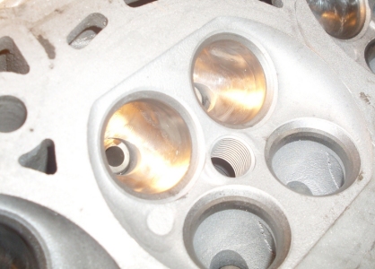
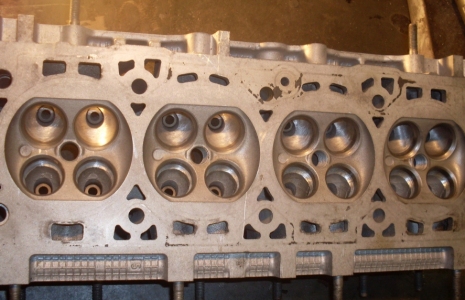
The finished intake ports are shown in the pictures.


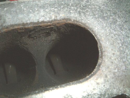
Modifications of the cylinder head - exhaust side
The exhaust side had very small seat inside and port diameters compared to the valve side. In this case, more flow could be achieved even by decreasing the valve diameter! Baybe the factory had some specific reason to use this kind of setup - perhaps reducing hydrocarbon emissions in order to reduce direct cross-flow from intake port to exhaust port during the overlap period.
The exhaust and intake valves had both quite the same diameter, which is also quite uncommon. On the other hand, the pressure-charged engine will benefit from good exhaust side flow.

The pictures above show the difference between desired and present exhaust seat inner diameters. Also change in the diameter is shown.
Exhaust seats were opened to the desired diameter. On this phase, material is removed only to achieve the diameter needed - this means cutting in the direction of the valve stem. The diameter should be 0,9 times the valve diameter, if there is enough seat thickness to work with.

After the seats have been opened to correct inner diameter, there is a large step in the valve pocket because the port is still small. The valve pocket and port must both be opened to correspond with the new seat measures. The port diameter compared to the seat diameter can be larger than on the intake side, but this also will depend on what kind of behavior is expected from the engine. Slightly smaller exhaust port will help the turbo to spool up at lower RPM.


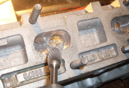
After the valve pocket of the exhaust side has been modified, its surface is very rough. Smoothing is done with grinding stone and flapwheel driven by a die grinder.


The exhaust port diameter is enlaged at the next, because of the changed inner diameter of the exhaust seat.

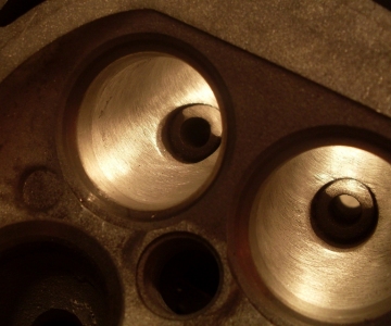
The ready exhaust ports are shown in the pictures below.


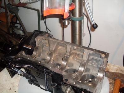
The cylider block
After the engine has been completely stripped, the cylinder block was washed thoroughly at the workshop at the same time when it was machined. All the rust and residues of paint was wire-brushed away. The block was also painted.


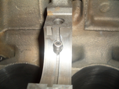
Cooling the pistons with proper oil spray jets is important particularly on pressure-charged engines, instead of only the holes drilled into the connecting rods. It was necessary to put the oil jets into this engine anyway, since the rods being used do not have any spray holes in them.
The block was put on the movable table below an upright drill and the proper mounting angle for the jets was achieved by putting a piece of wood under one end of the block.

The oil galleries should be blocked before the work, in order to prevent any steel splinters to enther there.


Because drilling must be started from a difficult place, some recess had to be machined into the surface, for starting point.
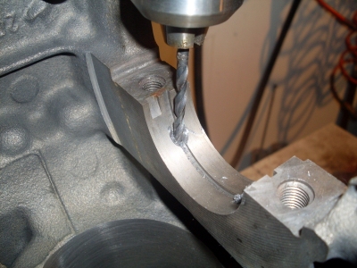

At the first, a hole will be drilled through. This will have the same diameter that the discharge tube of the jet has. This part of the jet will become visible on the main bearing boss, below the cylinder. After this hole is ready, the recess for the jet body is drilled with suitable drill. With the Fiat Tipo/Tempra 1.6 SOHC jets being used on this engine, those measures were 4,3 and 7,5mm.
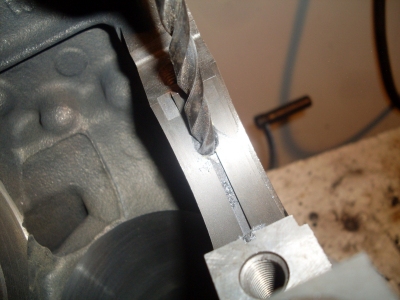


For finding the correct depth for the mounting recess, a gauge is done from steel wire. Care must be also taken to maintain enough material thickness of the block.

The ready mounting for the jet is shown in the picture below. Also the jet angle is shown on another picture (the jet is not completely pressed in place in the picture - in that case it wouldn't show any more).