Background
At the end of the Eighties, Fiat developed a 16v head that has an enormous tuning potential. The first engines were put into Lancia Thema, Delta Integrale and Fiat Tipo, but later, also many other high-power models become equipped with this power unit.
Additional information of the engine type can be found here.Dismantling the original 16v engine
I bought a Thema 16v ie engine from my friend many years ago. My friend bought the car from an insurance company because the car was probably stolen and crashed - result was that the bottom end of the engine was dead due to sudden lack of coolant or oil. However, I found many still usable parts from the engine, along with the desired 16v head. That was in good condition. Just to make sure, it was checked and pressure tested at local machine shop. My friend continued his Thema restoration project and bought a second-hand engine from Germany.


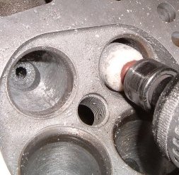
The structure of the head can be seen from the pictures below. It has 34,5 / 28,5mm valves as standard. For a normally aspirated engine, those sizes are perfectly acceptable but the pressure charged engines would benefit from having slightly larger exhaust valves. The stock port finish is quite rough, which is common on the modern heads made in fully automatized factories. I heard from some enhusiast that the head flows 227hp in it's standard form, and 240hp after light porting job.
The turbo versions of this engine have sodium filled exhaust valves. This one does not, so I decided to replace them...


Head modifications
The exhaust valves were made from 30mm Nimonic blanks, the finished valve size was 29.7mm. The stock intake valves were retained, only some reshaping was carried out. Two new intake valves and valve guides were fitted because they were damaged.


The size of the exhaust valve was selected so that it could be fitted by machining the stock exhaust seats. On the other hand, fitting larger exhaust valves do not offer much benefit because the combustion chamber wall is on the way. The stock valve seats already are three angle ground so there is not much room for further improvement in that sense.


Then, it was time for the actual porting job, for the intake ports. A die grider with various accessories was used. The head has quite large ports as standard, so enlarging them further is not necessary unless bigger valves and seats are used. As usual on factory-made cylinder heads, the intake diameters of both intake and exhaust seats were quite small, compared to the valve head sizes. The intake seat was cut from 30mm to 31mm, and the exhaust seat from 24.5mm to 26mm. Actually, the larger exhaust valve would need even larger seat diameter, but this would leave the seat too thin.


A tungsten carbide burr was used to remove casting roughness and ridges from the intake ports. At the same time, the valve pocket was reshaped so that the transition to the valve seat area was smooth. After that, a grinding stone was used to remove the surface roughness. It is vital to use some cutting fluid to prevent the stone from clogging. Alcohol-based solvents are good for this.


The grinding stone leaves scratchy surface, and this should be smoothed down using small-sized flapwheels. 80 grit is perfect for that. At the same time, the port gets its final shape. The best measurement device for finishing the port is finger!


The flapwheel leaves the surface very smooth, but usually it is advantageous to finish the ports manually with aluminium oxide cloth. The surface quality can then be controlled best. Again, 80 grit is a good choice.

The entry side of the intake ports was ported similar way, using carbide burrs, grinding stones and finally flapwheels and manual grinding. The most practical tool for a long, cylindrical-shaped intake port is the homemade one made from 6mm split rod and a piece of aluminum oxide cloth. The port divider edge is rounded, not knife-edged!


The exhaust port needed to be slightly enlarged, because of the bigger exhaust valve size. Additionally, a supercharged engine benefits from better-flowing exhaust side because the intake charge that is forced into cylinders with overpressure, generates more exhaust gases. With turbocharged engines, there is also an advance from getting the exhaust gases to the turbine as hot as possible, because their enthalpy is great then.


There was a huge mismatch between the machined exhaust seats and stock exhaust valve pockets. The valve pockets were started to modify with carbide burr. When the pocket nearly reached its final shape, the grinding was continued with grinding stone. The exhaust port was made little wider at the point where the valve guide is. Finally, the exhaust ports were finished using flapwheel and manual grinding.


The exhaust port surface quality was chosen relatively fine, because there is no benefit from swirling. On the other hand, mirror finish was not desired because a slightly coarse surface finish assists some carbon build-up that acts as thermal insulation.

The bottom end
Because the engine will be fitted into RWD car, an early 2L TC bottom end is obvious choice. These can be found, for example, from Fiat 131 and 132. This engine is from the 131, and the engine is bought in running condition. It has been standing a long time, though.


Fortunately, no nasty surprises were found when dismantling the engine, apart from the flywheel. It is from 1.6-litre engine and it seems like it has been modified to fit using electric drill. Some bearings are slightly damaged, it seems like some material has corroded away. High sulphur content of old oil, perhaps?


The crank was in perfect condition, according to the measurement and visual inspection. The bores were worn a little, it seems like the engine has quite high mileage. Some ovality was detected in cylinder #4.


After dismantling, the block was cleaned. Two modifications were done: four rear oil passages for the head were blocked, because only 2 front passages will be needed with the 16v head. Fuel pump lobe was removed from the auxiliary shaft - after that, there is no need to worry about the timing of that shaft - the lobe cannot be hit by #2 conrod any more.


The supercharger
The supercharger going to be used on this engine is visible in the pictures below. It is Eaton M45, and it is suitable for up to 0.5 bar (7 PSI) boost on this kind of engine.


The Eaton was originally equipped with multi-rib belt pulley. This kind of a belt is problematic because pulleys and belts are not available in any measures. Industry standard cogged belt is much better in that sense, and this belt type was selected for the application. The pulley cog count for the supercharger is 18, and 40 for the crank. The belt has standard 10mm pitch, and it is 25mm wide.


A suitable mounting bracket for the supercharger was fabricated. It bolts directly into the block side. It is surprising how difficult is to get the supercharger shaft and crankshaft parallel, and the pulleys in line at the same time...


